Linear vs Switching Power Supply Efficiency Under Load
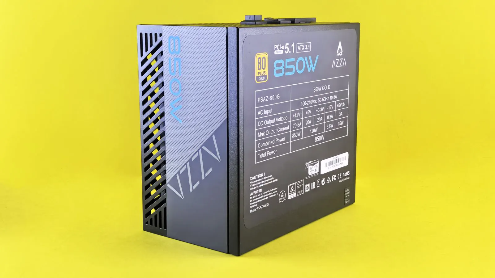
Linear supplies waste more energy as heat at high loads, while switching units remain efficient across wider load ranges. Selecting the right topology depends on ambient temperature, power quality needs, and the specific load profile of your industrial equipment.
- Linear supplies convert AC to DC with minimal ripple but reject excess energy as heat.
- Switching supplies use high-frequency components to step voltage, resulting in lower conduction and switching losses.
- Load factor directly impacts efficiency. Low loads reduce switching losses, while high loads stress thermal limits.
- Ambient temperature dictates the cooling strategy needed to maintain reliable operation.
- Noise and power quality requirements often favor linear topologies despite lower efficiency.
Why Efficiency Varies by Topology
Power supply efficiency is defined as the ratio of useful output power to total input power, expressed as a percentage. The topology of the unit determines how electrical energy moves from the mains or DC source to the load. Two primary approaches dominate industrial and laboratory equipment: linear regulation and switching conversion.
A linear supply uses a transistor to act as a variable resistor or current source. It holds the output voltage at a fixed level by absorbing the difference between the higher input voltage and the lower required output voltage. This difference, known as the dropout voltage, is dissipated as heat within the pass transistor. For example, if a 24V DC supply is powered by a 32V DC input, the pass transistor must drop 8V across its terminals. If the load draws 5A, the transistor dissipates 40W of heat. This heat must be removed by a heatsink to prevent thermal shutdown.
A switching supply operates differently. It converts the input voltage into a high-frequency square wave using a semiconductor switch, such as a MOSFET. This pulse is passed through a transformer or inductor and then rectified into DC. The control circuit adjusts the duty cycle of the switch to regulate the output. Because the energy is transferred through magnetic components and regulated at high speed, the total energy loss per cycle is significantly lower than in a linear design. A switching supply can accept many input voltages, such as 120V or 230V AC, and step it down to a low voltage like 5V or 12V DC with high efficiency.
The mechanism creates distinct efficiency profiles. Linear supplies are inefficient when the input voltage is much higher than the output voltage. The efficiency drops linearly as the voltage difference increases. Switching supplies maintain high efficiency over a broad range of input voltages and load levels. They are particularly effective when stepping down high voltages to low voltages, a task where linear supplies waste the most power.
How Load Factor Changes the Picture
Load factor describes the ratio of actual power delivered to the load compared to the rated maximum capacity of the supply. A 1000W unit running at 800W operates at an 80% load factor. Efficiency curves for both topologies shift as this factor changes, and understanding this shift is critical for selecting the right hardware.
Linear supplies lose efficiency rapidly as load decreases. The pass transistor continues to dissipate the same voltage drop regardless of how much current the load actually requires. At 20% load, the useful power delivered to the load is low, but the heat generated by the pass transistor remains significant because the voltage drop is unchanged. The heat generated per watt of useful output increases dramatically. In extreme cases, a linear supply at very low load can be less efficient than a switching supply at full load, simply because the fixed heat loss of the linear stage dominates the small amount of useful power.
Switching supplies behave differently. Their efficiency typically peaks near full load or slightly below it, but it drops only gradually at lower loads. The control circuitry, transformer, and magnetic components continue to draw some power, but the switching losses decrease as the load lightens. At very low load factors, the quiescent current of the control IC and standby circuits becomes a larger percentage of the total input power. For a small 50W switching supply running at 1W, the internal electronics might consume 0.5W, resulting in a 50% efficiency. For a 10kW industrial supply running at 100W, that same internal consumption is negligible, and efficiency remains high.
Switching Losses and Component Selection
Switching losses occur in two main places. The MOSFET or IGBT switches on and off. Each transition causes a brief period where high current and high voltage exist simultaneously across the device. This overlap creates energy loss during the turn-on and turn-off times. The transformer core also experiences hysteresis and eddy current losses during each magnetic cycle. These losses accumulate rapidly as the switching frequency increases.
Higher switching frequencies reduce the physical size of inductors and transformers. They also lower the core losses per cycle because the magnetic field changes more rapidly, allowing for smaller magnetic materials. However, higher frequencies increase the switching losses in the semiconductor devices. The gate drive circuit must charge and discharge the MOSFET gate capacitance more often, and the overlap of voltage and current during the transition becomes more frequent. The design team must balance frequency against component efficiency. A design running at 100kHz might use a smaller transformer but require a more efficient MOSFET than one running at 50kHz.
The choice of output capacitor matters too. A large electrolytic capacitor stores energy and supplies current during the peak of the switching cycle. It has a low equivalent series resistance, which helps stabilize the output voltage. However, electrolytic capacitors have a finite lifespan and their impedance increases as they age. A film capacitor offers lower loss and better thermal stability but costs more and holds less charge per volume. The combination of these parts determines how much of the input energy reaches the load. A poorly chosen capacitor can cause voltage ripple, which forces the load to reject energy, effectively reducing the system efficiency.
Thermal Management and Ambient Limits
Heat is the primary failure mode for power supplies. Linear supplies generate more heat per watt of output. A 500W linear supply may reject 300W or more as heat, depending on the input voltage. This waste heat raises the internal temperature. If the ambient temperature is high, the thermal margin shrinks. The thermal design of a linear supply is often dictated by the heatsink size. A large heatsink allows the supply to run cooler, but it increases the physical footprint of the unit.
Switching supplies generate less waste heat, but the heat is concentrated in specific components. The MOSFETs and diodes sit on a heatsink. The transformer and inductor dissipate heat into the surrounding air. If the unit sits in a crowded cabinet, airflow may be restricted. The power supply may overheat even if the ambient temperature is moderate. In a sealed enclosure without ventilation, the internal temperature can rise well above the ambient, causing components to exceed their maximum operating temperature.
The cooling strategy must match the topology. Linear supplies often require large heatsinks or forced air cooling. Switching supplies rely on internal fans or passive convection. When selecting a unit for a hot environment, check the derating curve. The maximum output power may drop as the ambient temperature rises. For example, a supply rated for 100% load at 25C ambient might be derated to 80% load at 50C ambient. Ignoring this derating can lead to premature failure, as the components operate continuously above their thermal limits.
Power Quality and Noise Considerations
Efficiency is not the only metric. Linear supplies provide extremely clean DC output. The ripple current is minimal. This makes them suitable for sensitive analog circuits, precision measurement instruments, and high-frequency communication equipment. The switching supply introduces high-frequency noise onto the output. The rectifier and filter components do not remove all the switching frequency energy. Some of this energy appears as ripple on the output bus and as electromagnetic interference on the input lines.
A well-designed switching power supply filters this noise using LC filters on the input and output. The inductor opposes rapid changes in current, and the capacitor shunts high-frequency noise to ground. But the noise floor is still higher than that of a linear supply. If the load is sensitive to electromagnetic interference, the switching noise may cause instability. In precision test equipment, the switching noise can corrupt measurements, leading to false data. The design team might add a linear regulator after the switching stage. This hybrid approach improves efficiency over a pure linear supply while maintaining the low noise of a linear device. The switching stage handles the bulk of the power conversion, and the linear stage polishes the output voltage.
Comparison of Topologies
| Option | Best for | Limitations |
|---|---|---|
| Linear Supply | Sensitive analog circuits, low noise applications, low output power | Low efficiency at high loads, high heat generation, limited input voltage range |
| Switching Supply | High output power, wide input voltage, space-constrained cabinets | Higher noise floor, complex filtering required, potential EMI issues |
| Hybrid Supply | High power with low noise requirements, precision measurement | Higher cost, more complex design, slightly lower efficiency than pure switching |
| Isolated Switching | High safety requirements, different input and output voltage levels | Transformer size increases with power, additional magnetic losses |
| Unregulated Supply | Simple DC loads, battery charging, low cost applications | Output voltage varies with load and input, poor voltage regulation |
How to Select the Right Efficiency Profile
Start with the load profile. If the equipment runs at a steady 80% to 95% load, a switching supply will likely be more efficient. If the load fluctuates widely, especially dropping below 20% for long periods, the efficiency advantage of the switching supply shrinks. You need to calculate the average efficiency over the operating cycle, not just at peak load. A unit that is 92% efficient at 100% load but 60% efficient at 10% load may waste more energy over a day of operation than a unit that is 85% efficient at 100% load and 80% efficient at 10% load.
Next, check the noise requirements. If the application uses a microcontroller or a sensor, measure the noise tolerance. A switching supply with poor filtering may inject noise into the signal chain. A linear supply avoids this problem but wastes energy. In some cases, a switching supply with a high-quality LC filter and a low-noise linear regulator at the output provides the best balance. The hybrid approach allows you to use the efficient switching stage for the main power conversion and the linear stage for the final voltage regulation.
Finally, evaluate the thermal environment. A unit in an open cabinet has good airflow. A unit in a sealed enclosure needs a fan or a heatsink that extends outside. The ambient temperature in the server room or machine shop matters. If the space is hot, the linear supply will struggle to maintain its rated output. The switching supply has a higher thermal margin and can handle the temperature better, provided it has adequate ventilation. Check the fan specifications if the unit uses forced air. A failed fan can cause a switching supply to overheat and shut down, which can disrupt critical operations.
When you select a power supply, look at the efficiency curve provided by the manufacturer. It shows the percentage of input power converted to output power at different load levels. A unit rated at 90% efficiency at full load may be 80% at 10% load. Match the curve to your actual operating conditions. Do not rely on the peak efficiency figure alone. The real world is rarely at peak load. You must consider the entire operating range to ensure the supply performs as expected and meets your energy efficiency goals.
Frequently asked questions
What is a typical efficiency range for linear and switching power supplies?
Linear supplies often operate between 60% and 85% depending on the voltage drop and load. Switching supplies can reach 85% to 95% under optimal conditions, though this varies with component quality.
How does load factor affect switching losses?
Switching losses decrease as the load factor drops because the MOSFETs switch for less time per cycle. However, the fixed power drawn by the control circuitry becomes a larger percentage of the total input power at low loads.
Can a switching power supply replace a linear supply in sensitive applications?
Often, yes. Modern switching designs use multi-stage filtering to reduce noise below the limits of most digital circuits. However, for high-precision analog equipment, a linear supply or a hybrid design provides a safer noise floor.
What is the impact of ambient temperature on power supply efficiency?
Higher ambient temperatures reduce the thermal headroom of the cooling system. This may force the unit to derate its output power to prevent overheating. It does not change the electrical efficiency percentage, but it affects the maximum power the unit can deliver.
How do I calculate the heat generated by a power supply?
Use the formula: Heat = (Input Power - Output Power). Input power is the load power divided by the efficiency percentage. For example, a 500W output at 80% efficiency requires 625W of input power, generating 125W of heat.