Explainer: How Isolation Affects DC-DC Ripple and Noise

Isolated DC-DC converters use galvanic separation to block ground loops, but this physical barrier changes how ripple and noise propagate. Understanding these mechanisms helps buyers select the right topology for sensitive analog or digital loads.
- Galvanic isolation blocks direct current paths but shifts noise coupling to capacitive and magnetic channels.
- Common-mode noise often dominates the output of isolated DC-DC modules compared to non-isolated designs.
- Output capacitance and layout choices determine how effectively the converter filters high-frequency switching artifacts.
- Signal integrity requires matching the isolation method to the specific noise profile of the connected load.
What Is Galvanic Isolation in Power Conversion
Galvanic isolation breaks the electrical connection between the input and output circuits. In an isolated DC-DC converter, the power stages on the input side and the power stages on the output side never share a physical conductor. A transformer or an optocoupler transfers energy or control signals across this gap.
This separation protects sensitive electronics from ground loops. It also prevents a fault on the high-voltage side from propagating directly to the low-voltage logic side. For a buyer, isolation is often a mandatory feature for safety standards in industrial automation. The trade-off is that the converter must manage the energy transfer differently than a non-isolated topology.
The physical barrier creates a specific set of electrical limitations. The isolation gap acts like a capacitor. It allows high-frequency displacement current to flow while blocking direct current. This capacitive coupling is the primary path for common-mode noise to reach the output side. The strength of this coupling depends on the capacitance of the isolation barrier and the frequency of the switching noise.
How Isolation Changes the Noise Profile
Non-isolated converters share a ground reference. Noise on the output is usually dominated by differential-mode signals, which travel along the power lines between the positive and negative rails. In an isolated converter, the output ground is floating relative to the input ground. This creates a new channel for noise.
Common-mode noise appears as a voltage difference between the output ground and the input ground. It also appears as voltage spikes on the output rails relative to a remote reference. For a digital circuit, this can cause logic threshold violations. For an analog circuit, it can modulate the reference voltage and degrade signal-to-noise ratio.
The switching frequency of the DC-DC converter sets the fundamental frequency of the noise. In an isolated design, the transformer core and windings introduce magnetic coupling. If the core is saturated or if there are air gaps, high-frequency components can leak. The isolation barrier, whether a plastic film or a ceramic layer, has a finite dielectric strength and parasitic capacitance. As the switching frequency rises, the impedance of this parasitic capacitance drops. The result is more common-mode noise leaking through the isolation gap.
Ripple Characteristics in Isolated Topologies
Ripple is the low-frequency variation of the output voltage after the switching noise has been filtered. In an isolated DC-DC converter, ripple is influenced by the transformer ratio and the output filter. The transformer transfers the switched waveform to the secondary side. The secondary rectification and filtering stages then shape this waveform into a steady DC output.
The ripple magnitude depends on the duty cycle of the switching operation and the impedance of the output filter. A larger output capacitor reduces ripple by storing energy during the off-time of the switch. However, adding too much capacitance can introduce resonance with the inductor. This resonance can amplify specific frequency components.
In isolated designs, the transformer leakage inductance also plays a role. Leakage inductance stores energy during switching transitions. This energy is not transferred to the secondary windings efficiently. It can cause voltage spikes on the secondary side. If the output filter is not designed to absorb this energy, the spikes appear as high-amplitude ripple on the output rails. The shape of the ripple waveform can therefore be more complex in an isolated converter than in a non-isolated one.
Signal Integrity Implications for Sensitive Loads
Signal integrity refers to the ability of a circuit to maintain a clean voltage level and timing profile. Isolated DC-DC converters are often used to power sensitive analog front-ends or high-speed digital interfaces. The noise profile of the power supply directly affects the performance of these circuits.
A floating output ground can cause ground shifts. If the load circuit has a reference point that is not isolated from the input ground, common-mode noise will appear directly on the signal lines. This is particularly problematic in long cable runs, where the cable acts as an antenna. The common-mode voltage induced on the cable shield can couple into the signal conductors.
To mitigate this, the isolated DC-DC converter must be designed with a specific output impedance in mind. Low output impedance helps reject noise sources. However, isolation increases the effective impedance of the power path compared to a non-isolated design. The isolation capacitance adds a parallel path for high-frequency noise. This can degrade the transient response of the supply. A sudden load change can cause a voltage dip that is slower to recover than in a non-isolated design.
Worked Example: Powering an Analog Sensor Array
Consider a system that powers a bank of analog pressure sensors from a 24V DC bus. The sensors have a 16-bit resolution and are very sensitive to noise. The system requires an isolated power supply to prevent ground loops between the sensor head and the main controller.
The engineer selects an isolated DC-DC converter rated for 24V input to 5V output. The converter uses a high-frequency switching topology to keep the physical size small. The transformer provides galvanic isolation. The output stage includes a Schottky diode rectifier and a low-ESR ceramic capacitor.
During operation, the output voltage shows a small ripple voltage. The ripple frequency matches the switching frequency of the converter. The amplitude of the ripple is low enough to meet the sensor specifications. However, the engineer notices that the common-mode voltage between the sensor ground and the main controller ground fluctuates at the switching frequency.
This fluctuation is caused by the capacitive coupling through the transformer isolation barrier. The sensor circuit is not perfectly isolated from the main ground. The fluctuating common-mode voltage modulates the sensor reference. The solution is to add a ferrite bead on the sensor power lines. This bead attenuates the high-frequency noise before it reaches the sensitive analog circuits. The ripple voltage on the output rails remains unchanged, but the signal integrity improves significantly. The sensor data becomes cleaner, and the 16-bit resolution is fully use.
Selection Criteria for Buyers
When selecting an isolated DC-DC converter, the output quality must be evaluated against the specific noise requirements of the load. The data sheet will list the output ripple and noise, but it may not detail the common-mode noise levels. You should request test data for the specific frequency range of interest.
Consider the isolation capacitance. A lower isolation capacitance reduces common-mode noise coupling. This is typically achieved with a larger physical gap or a lower dielectric constant material. However, this can increase the transformer size. The thermal design must also be considered. Isolated transformers have higher losses than non-isolated inductors. The power dissipation affects the operating temperature, which in turn affects the output voltage regulation.
The output filter design is critical. A simple L-C filter may not be sufficient for high-frequency noise. A multi-stage filter or a feedthrough capacitor may be needed. The impedance of the output filter must be checked against the noise spectrum. If the filter has a resonance peak that aligns with the switching frequency, the ripple will be amplified.
Finally, evaluate the layout of the converter module. The physical placement of the transformer, capacitors, and inductors affects the parasitic capacitance and inductance. A well-designed module will minimize these parasitics. The PCB layout of the converter is a significant factor in the final noise performance. A module with a good layout will show lower common-mode noise than a module with a poor layout, even if the component values are identical.
| Parameter | Effect on Output Quality | Buyer Action |
|---|---|---|
| Isolation Capacitance | High values increase common-mode noise coupling | Request capacitance data and test at operating frequency |
| Switching Frequency | Higher frequency reduces ripple magnitude but increases common-mode noise | Match frequency to load noise tolerance |
| Output Capacitance | Reduces ripple but can introduce resonance | Verify impedance profile across the frequency range |
| Transformer Leakage Inductance | Causes voltage spikes during switching transitions | Check for spike suppression in the output stage |
| Output Impedance | Determines transient response and noise rejection | Measure impedance at the load connection point |
Practical Checks for Field Verification
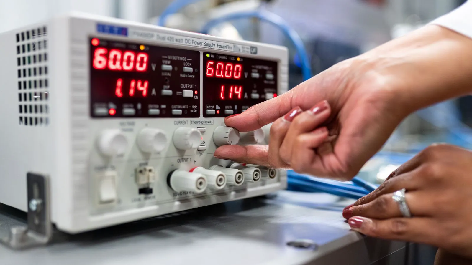
Before finalizing a power supply selection, run a verification test on the actual system. Measure the output voltage with a high-resolution oscilloscope. Use a short probe lead or a differential probe to avoid picking up environmental noise. Observe the ripple waveform at the switching frequency.
Check the common-mode voltage between the output ground and the input ground. Use a differential amplifier to measure this voltage. This measurement will reveal the noise that is not visible on a standard multimeter. If the common-mode noise exceeds the tolerance of the load circuit, the supply is not suitable for the application.
Perform a load transient test. Sudden changes in load can cause voltage dips or spikes. The recovery time indicates the effectiveness of the output filter. In an isolated converter, the recovery time may be longer due to the energy storage limits of the transformer. Ensure that the recovery time meets the requirements of the load circuit.
Review the thermal profile of the converter. Measure the output temperature under full load. Excessive heat can degrade the insulation of the transformer windings. This can reduce the isolation strength over time. A reliable supply must maintain its isolation rating under the maximum operating temperature.
Frequently asked questions
Does an isolated DC-DC converter always produce more noise than a non-isolated one?
Not necessarily. Isolation changes the type of noise coupling, shifting emphasis to common-mode signals. The total noise level depends on the specific topology and output filter design.
How does isolation affect the output ground reference?
The output ground becomes floating relative to the input ground. This prevents ground loops but introduces a common-mode voltage that must be managed.
Can I reduce ripple by adding more output capacitance?
Adding capacitance reduces the amplitude of the ripple voltage. However, it can introduce resonance with the inductor. The total impedance profile must be checked.
What is the main difference between differential-mode and common-mode noise in isolated supplies?
Differential-mode noise travels between the positive and negative rails. Common-mode noise appears between the output ground and a remote reference, often due to capacitive coupling.
How do I verify the signal integrity of an isolated DC-DC converter?
Measure the common-mode voltage between the output ground and the input ground using a differential amplifier. Check the output impedance and the ripple waveform at the load.