Isolated AC-DC Power Supplies: Why Isolation Matters in Industry
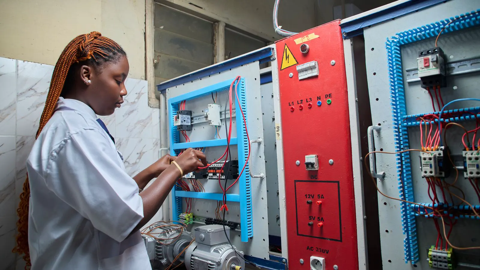
Isolated AC-DC power supplies decouple input and output circuits, preventing ground loops and electrical noise from reaching sensitive loads. This design choice is often required for safety, reliability, and compliance in industrial settings.
- Isolation creates a physical barrier between the mains input and the DC output, breaking ground paths.
- It reduces the risk of electric shock and protects sensitive electronics from voltage spikes.
- Selection depends on load sensitivity, safety standards, and the need for noise immunity.
- Isolated units are generally heavier and cost more due to the extra transformer and components.
An isolated AC-DC power supply uses a transformer or similar device to separate the primary side from the secondary side. The mains voltage enters the unit, is stepped down or up, and then rectified into DC. Because there is no direct electrical connection between the input and output, the output can float relative to earth.
This design is standard in many industrial environments. It protects the load from ground loops, where current flows through unintended paths due to differences in earth potential. It also limits the spread of noise from the mains grid. For engineers, the decision to choose isolation is rarely about power rating alone. It is about system integrity.
What is isolation in an AC-DC context?
In a non-isolated unit, the DC output is often referenced to the AC neutral or earth. This is simpler and cheaper. In an isolated unit, the output is referenced to the chassis or a floating point. The transformer provides electrical separation.
The isolation barrier has two parts. The first is the physical gap between primary and secondary windings. The second is the insulation that prevents arcing or leakage. The combined effect is a rated isolation voltage, which indicates the maximum voltage the barrier can withstand without a breakdown.
Engineers check the isolation rating against the application. A low-voltage control circuit might need a basic barrier. A high-voltage motor drive or medical device requires a much stronger separation.
How isolation affects safety
Ground loops are a common failure mode. When two equipment chassis are grounded at different points, a small voltage difference can appear between them. In a non-isolated system, this voltage can flow through the load and into the operator or the control logic.
Isolation removes this path. The DC output does not share a common ground with the mains. Current cannot flow from the output back to earth through the load. This reduces the risk of shock and protects the equipment from damage caused by potential differences.
In industrial plants, earth potentials can vary due to large currents in nearby grounding systems. A control cabinet might be grounded at the main substation. A remote sensor might be grounded at a different point. The voltage difference between these grounds can be significant. Isolation prevents this difference from appearing across the sensitive electronics.
Noise immunity and signal integrity
Mains grids are noisy. Motors, variable frequency drives, and switching power supplies inject high-frequency transients into the wiring. These transients can couple into the power supply and pass through to the load.
In a non-isolated unit, the output is connected to the input ground. Noise on the neutral or earth conductor can appear directly on the DC output. This causes voltage ripple, logic errors, or sensor drift.
An isolated unit acts as a filter. The transformer blocks low-frequency common-mode noise. The isolation barrier prevents high-frequency transients from jumping from primary to secondary. The result is a cleaner DC output.
This is critical for precision instruments and communication systems. A sensor that requires a stable reference voltage will fail if the supply output fluctuates. Isolation provides the stability that non-isolated units cannot guarantee.
How isolation impacts sourcing decisions
When sourcing an isolated AC-DC power supply, the primary spec is not just voltage and current. It is the isolation rating and the protection class.
Engineers must match the isolation level to the safety requirements of the load. A Class A application might need basic isolation. A Class B application requires double insulation. A Class III application is protected by barriers and may not be suitable for general industrial use.
The physical size and weight also change. A transformer adds bulk. The heat dissipation from the transformer must be managed. In tight enclosures, an isolated unit may require more ventilation or a larger housing than a non-isolated unit of the same power rating.
Cost is another factor. Isolated units are more expensive because they contain more components and more insulation material. The price difference is usually justified by the reliability and safety benefits. However, for simple DC loads that do not require isolation, a non-isolated unit may be a better fit.
Worked example: A factory sensor network
Consider a factory line with a temperature sensor array. The sensor head is located near a large conveyor motor. The motor is connected to a variable frequency drive. The sensor controller is located in a central cabinet.
The sensor head uses a 24V DC supply. Without isolation, the controller ground is connected to the mains ground. The motor drive injects noise into the ground system. This noise appears on the sensor supply. The temperature readings drift. The control system misreads the temperature and shuts down the line.
With an isolated supply at the sensor head, the output is floating. The noise on the motor ground does not couple to the sensor output. The sensor controller provides a stable reference. The readings remain accurate. The line continues to run.
The isolation barrier also protects the sensor head from any earth potential difference between the motor and the central cabinet. The sensor head is grounded locally. The central cabinet is grounded at the main substation. The difference between these grounds is blocked by the isolation.
Isolation vs. non-isolation: When to choose each
The choice depends on the load and the environment.
| Feature | Isolated Unit | Non-Isolated Unit |
|---|---|---|
| Ground Loop Protection | Yes | No |
| Noise Immunity | High | Low |
| Safety Rating | Higher | Lower |
| Size and Weight | Larger | Smaller |
| Cost | Higher | Lower |
| Typical Use | Sensitive electronics, medical | Simple DC loads |
A non-isolated unit is suitable for loads that are not sensitive to noise or ground loops. A simple LED driver or a heating element does not care about ground potential differences.
An isolated unit is required for loads that need a stable reference. Precision analog circuits, communication equipment, and medical devices all benefit from isolation. The isolation barrier prevents external electrical events from affecting the internal circuitry.
Selection checklist
- Determine the safety class of the application. Check the relevant standards for the specific industry.
- Measure the noise environment. High-frequency noise from nearby equipment indicates a need for isolation.
- Check the grounding scheme. If the equipment is grounded at multiple points, isolation is recommended.
- Evaluate the physical space. Isolated units are bulkier. Ensure the enclosure has room for the transformer and heat sink.
- Verify the isolation rating. It must exceed the maximum voltage expected in the worst-case scenario.
- Consider the service life. Isolated units are generally more robust. They last longer in harsh environments.
Common mistakes
Engineers often choose a power supply based on voltage and current only. They ignore the isolation requirement. This leads to field failures that are difficult to diagnose.
Another mistake is placing an isolated unit in a non-isolated system. The output is floating, but the chassis is grounded. This defeats the purpose. The isolation is only effective if the output is not referenced to earth.
A third mistake is ignoring heat. The transformer in an isolated unit generates heat. If the enclosure is poorly ventilated, the unit will overheat and shut down. Thermal management must be designed in from the start.
Final considerations
Isolation is a design choice that affects safety, reliability, and performance. It is not just a spec line. It changes how the system behaves in the real world.
For industrial applications, isolation is the default. The cost and size penalty are usually worth the protection. For simple loads, a non-isolated unit may be sufficient. The key is to match the supply to the load.
Engineers must understand the electrical environment. They must know the grounding scheme, the noise levels, and the safety requirements. With this knowledge, the choice between isolated and non-isolated becomes clear.
Frequently asked questions
What is the main difference between an isolated and non-isolated AC-DC power supply?
An isolated supply uses a transformer to separate the input and output circuits, preventing direct electrical contact. A non-isolated supply has a direct path between the input ground and the output.
Do all industrial power supplies require isolation?
No. Simple loads like heaters or basic motor drives may work without isolation. However, sensitive electronics and safety-critical systems usually require it.
How much extra cost does isolation add?
The cost difference varies by manufacturer and power rating. Generally, isolated units are more expensive due to the transformer and additional insulation.
Can I mix isolated and non-isolated supplies in the same system?
Yes, but you must manage the grounding carefully. Mixing them can create ground loops if not designed properly.
What is the best way to test for isolation?
Use an insulation resistance tester to measure the resistance between the primary and secondary terminals. It should be well above the minimum required value.